Ultrasound
The Ultrasound stress measurement technique is the only portable, non-destructive, through-thickness stress measurement technique and it is applicable to a wide range of materials.
Ultrasound waves (2 MHz - 10 MHz) are commonly used to detect flaws in engineering materials, however they can also be used for the measurement of stresses, applied and residual. The speed of ultrasound waves travelling through a material are affected by the direction and magnitude of the stresses present, which is called the acoustoelastic effect. Therefore the magnitude and direction of the stresses present within a material can be calculated by accurately measuring the change in time-of-flight of an ultrasound wave traveling through the stressed and unstressed regions of that material. For example, a stress of 1MPa in aluminium corresponds to a change in time-of-flight of roughly 1.7 ns. The acoustoelastic effect is most sensitive when the propagation path and particle motion of the ultrasound wave are parallel to the direction of stress being measured.
It is important to note that:
- The time-of-flight measurement in the stressed material will need to be compared against that in the unstressed material in order to obtain an absolute measurement of stress,
- The magnitude of stress measured will be an average of those acting between the emitter and receiver.
Sub-surface measurements

Snell's Law.
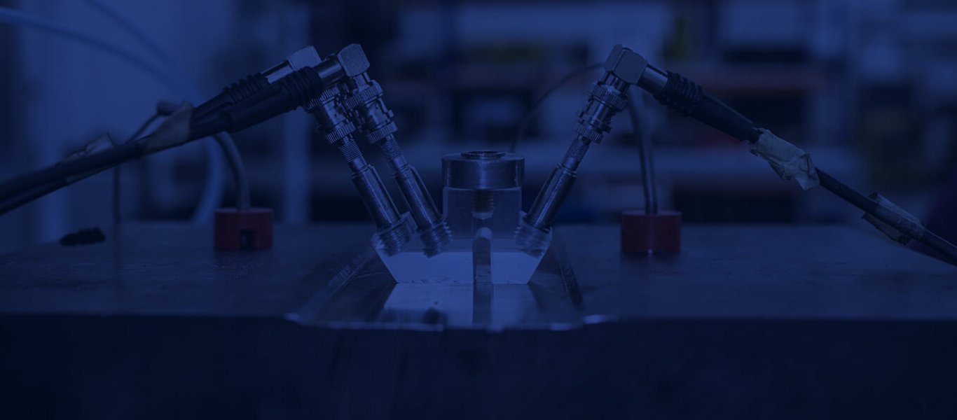
For sub-surface stress measurements, critically refracted Longitudinal waves (Lcr) are used, which travel just beneath and parallel to the specimen surface. Lcr waves are transmitted and received by attaching the transducer to a wedge of the correct inclination for the specimen material tested, as defined by Snell’s Law.
With:
Vss: Acoustic shear velocity of the specimen
VLs: Acoustic longitudinal velocity of the specimen
VSw: Acoustic shear velocity of the wedge
VLw: Acoustic longitudinal velocity of the wedge
The Lcr wave has the greatest sensitivity to stress due to both the propagation path and particle motion of the ultrasound wave being the same as the stress direction measured, i.e. the stresses acting in the direction between the emitter and receiver.

Ultrasound Wedge TOF Diagram.
Through-thickness measurements
Both Longitudinal and Shear waves can be used to measure the average stresses acting through the bulk of the specimen material in either the pulse-echo or transmission configuration. For through-thickness measurements it is essential that the measurement surfaces of the specimen are parallel.

Through Thickness Configuration
Longitudinal waves are used to measure the stresses acting in the through-thickness direction, i.e. in the direction of wave propagation and particle motion. Whereas Shear waves are polarised so that the particle motion is perpendicular to the direction of propagation and so can be used to measure the stresses acting parallel to the surface of the specimen in the direction of the particle motion. The more advanced technique of Shear wave birefringence uses two shear wave transducers acting across the thickness of a specimen to provide concurrent time-of-flight measurements for the stressed and unstressed states, assuming it is a homogeneous, isotropic material. Through-thickness stresses can be accurately and practically measured through specimens of up to 150mm thick
As well as being sensitive to stress, the speed of ultrasound waves through a specimen is also dependent upon the temperature and microstructure of the specimen. So, the change in time-of-flight, Δt, of ultrasound waves propagating through a specimen is:
Δt = ΔtAS + ΔtRS + ΔtT + ΔtM
Where ΔtAS is the change in time-of-flight due to applied stress changes, ΔtRS is the change in time-of-flight due to residual stress changes, ΔtT is the change in time-of-flight due to temperature changes and ΔtM is the change in time-of-flight due to microstructure changes.
Changes in applied stress and temperature can be corrected for, however changes in the microstructure of the specimen material is very difficult to account for. Therefore measuring within the same component, or an identical component, before and after residual stresses are present is the best method of keeping microstructural changes to a minimum and so providing accurate results. Microstructural changes affect the acoustoelastic coefficient, Lij, of the material, which is used in the final calculation of the applied and/or residual stresses thus:
Δσ = E . Δt ⁄ (Lij . t0)
Where Δσ is the change in stress, E is the material Young’s Modulus and t0 is the time-of-flight in stress free conditions.
Advantages of the Ultrasound Technique:
- Non-destructive technique;
- Laboratory or “on-site” measurements;
- Tri-axial residual stress measurements possible;
- High magnitude residual stresses are measured accurately;
- Measurement depths of up to 150mm possible;
- Applicable to a wide range of materials;
- Great for measuring applied stresses;
- Very quick measurement process.
Disadvantages of the Ultrasound Technique:
- Requires a stress-free reference measurement in order to provide absolute stress measurements;
- Very sensitive to microstructural changes;
- Provides an average stress measurement over a relatively large gauge volume;
- Through-thickness measurements require the component surfaces to be parallel;
- Not applicable to complex shaped components;
- Requires a good component surface finish;
- Spatial resolution is difficult to specify.
References & Further Reading:
- Egle, D. M., Bray, D.E. (1976) “Measurement of the Acoustoelastic and Third-Order Elastic Constants for Rail Steel,” Journal of the Acoustical of America 60(3):741744.
- Sajauskas, S. (2004) Longitudinal Surface Acoustic Waves, Kaunas University of Technology, Lithuania.
- Schneider, E. (1997) “Ultrasonic Techniques” 4:522-563. In: Hauk V (ed) Structural and Residual Stress Analysis by Non-destructive Methods, Elsevier: Amsterdam
- Wikipedia: Acoustoelastic effect
- Youtube: PZFlex - NDT: shear wave weld inspection from a phased array
- Youtube: Animations for Physics and Astronomy: Transverse and Longitudinal waves
- Sadeghi, S., Najafabadi, M. A., Javadi, Y., Using ultrasonic waves and finite element method to evaluate through-thickness residual stresses distribution in the friction stirwelding of aluminum plates, Materials and Design 52 (2013) 870-880, 2013


