X-Ray Diffraction
The X-ray Diffraction (XRD) technique is the most widely used non-destructive technique, specialising in the measurement of surface residual stresses.
Using laboratory-based or portable equipment, the XRD technique measures surface residual stresses to depths of up to 30μm by measuring the material's inter-atomic spacing.
Laboratory X-rays have wavelengths of the order of a few angstroms (Å), which is the same order of magnitude as the typical inter-atomic/inter-planar distances in polycrystalline solids. X-rays scattered from a polycrystalline solid can constructively interfere producing a diffracted beam. The angles at which the maximum diffracted intensities occur are measured. From these angles it is possible to obtain the inter-planar spacing, d, of the diffraction planes using Bragg’s law. If residual stresses exist within the sample, then the d spacing will be different from that of an unstressed sample (i.e. d0). The difference is proportional to the magnitude of residual stress present. In principle therefore, we use the grains as internal strain gauges for residual (or applied) stresses.
X-Ray Principle
Due to the low penetration depths of the laboratory XRD technique, measurements are restricted to the surface of materials, but benefit from the use of differential analyses techniques so that a stress-free reference (i.e. d0) sample is not required. For the most commonly used sin2ψ technique, the diffraction angle, 2θ, and hence the lattice spacing, d, can be determined for multiple inclination angles, ψ, of the sample surface, providing the relevant stress measurements.

Bragg's Law
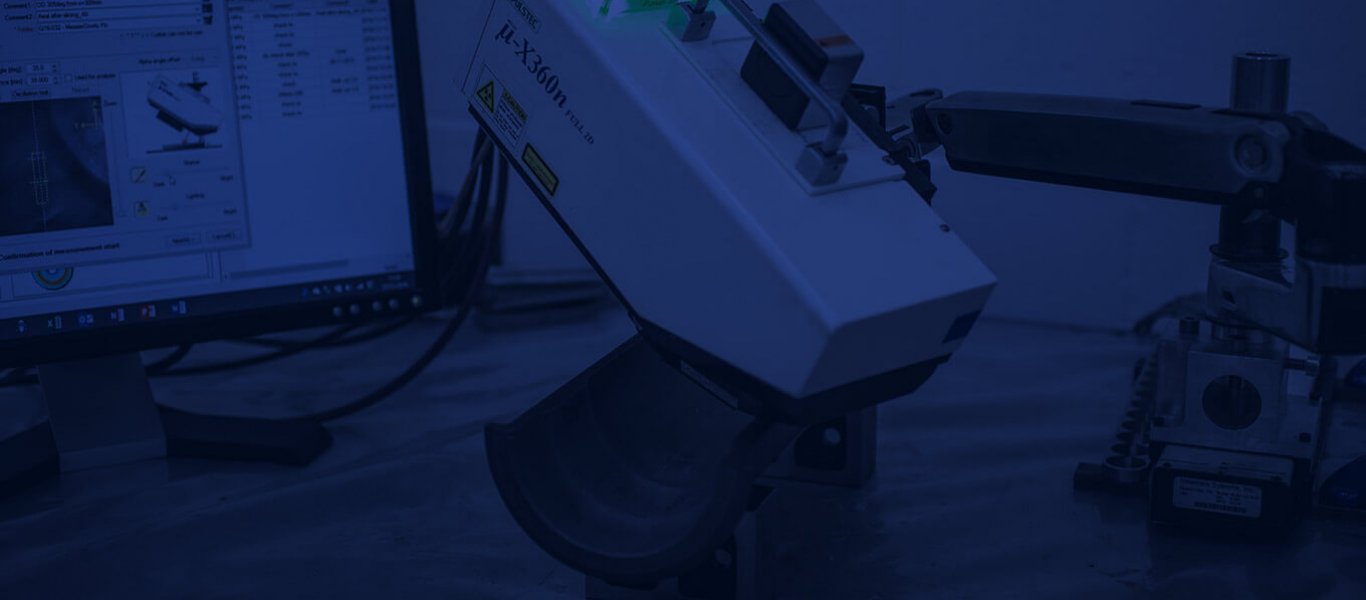
A new portable XRD machine has been developed that detects the complete debye ring of diffracted x-rays without the need for multiple inclinations of the sample surface. The complete debye ring provides lots of information about the texture in the sample and is analysed using the cos α technique to provide the lattice spacing, d, and hence the residual stresses.
Bi-axial residual stresses (i.e. σxx and σyy) are measured using XRD and are nominally accurate to ±20MPa in steel. The accuracy of the technique is heavily dependent upon good surface preparation and grain size/texture. Although classified as a surface measurement technique, measurements can be made at depths up to 1mm when combined with layer removal.

Shot Peening Residual Stresses
Advantages of the X-ray Diffraction Technique:
- Non-destructive technique;
- Laboratory or “on-site” measurements;
- Bi-axial (i.e. σxx and σyy) residual stress measurements;
- Small gauge volume and so great for measuring surface stress gradients;
- High magnitude residual stresses are measured accurately;
- Complex shapes can be measured providing rotation of the measuring head is not restricted;
- Nominal accuracy: 7MPa – Aluminium, 20MPa – Steel, 10MPa – Titanium;
- Very quick and easy to apply the process, and therefore cheap;
- Macro and micro stresses measured;
- Widely available.
Disadvantages of the X-ray Diffraction Technique:
- Measurement depths of only 10-20μm as standard, however when coupled with electro-polishing surface removal depths of up to 1–1.5mm are achievable;
- Only applicable to polycrystalline materials;
- Accuracy seriously affected by grain size and texture;
- A good component surface finish is essential, so may need delicate preparation.
References & Further Reading:
- Noyan, I. C., and Cohen, J. B., “Residual Stress Measurement by Diffraction and Interpretation”, Springer-Verlag, New York Inc., 1987.
- Fitzpatrick, M.E., Fry, A.T., Holdway, P., Kandil, F.A., Shackleton, J., and Suominen, L., “Determination of Residual Stresses by X-ray Diffraction”, Measurement Good Practice Guide No. 52, (Issue 2), NPL, UK, 2005.
- Schajer, G.S, Wiley, "Pratical residual stress measurement methods"
- Sasaki, T., et al., "Influence of image processing conditions of Debye Scherrerring images in x-ray stress measurement using an imaging plate", InternationalCentre for Diffraction Data, 1997.


